On this page
- How do Rockwell, Brinell, and Vickers hardness tests compare?
- What parameters differentiate Rockwell, Brinell, and Vickers hardness tests?
- Why is Rockwell hardness testing the production floor standard?
- Why is Brinell hardness testing the required method for castings and forgings?
- Why is Vickers hardness testing the universal lab method for welds and microstructures?
- How do I select the right hardness test method for a specific job?
- What are common specification pitfalls when selecting a hardness test?
- Key Takeaways
Rockwell vs Brinell vs Vickers: Hardness Test Comparison
Practical comparison of Rockwell, Brinell, and Vickers hardness tests: indenter types, loads, ASTM standards, applications, and how to choose the right method for QA, welding, and procurement.
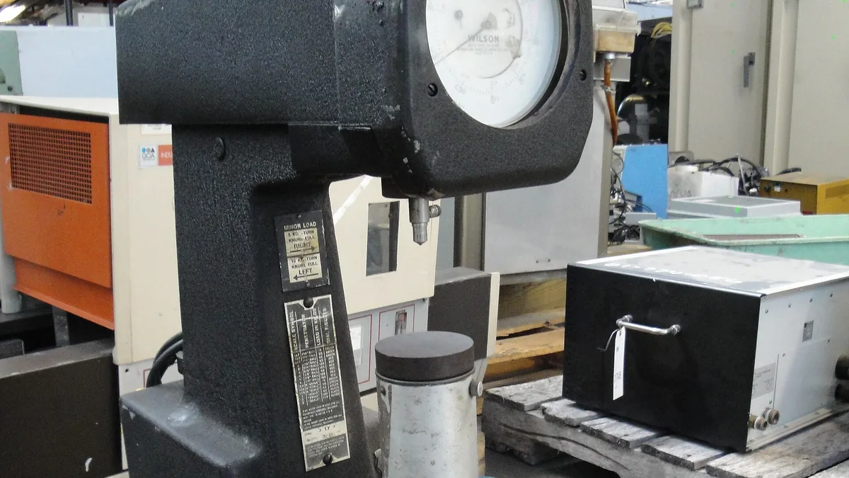

How do Rockwell, Brinell, and Vickers hardness tests compare?#
Rockwell, Brinell, and Vickers hardness tests differ in indenter geometry, applied load, and measurement principle, making the choice a specification-driven decision, not a preference. Selecting the wrong method can yield values that fail to correlate with the governing material standard, reject conforming parts, or overlook critical microstructural conditions. This comparison addresses the selection logic quality engineers, welding inspectors, and procurement teams apply daily: part geometry, material type, production speed, and the standard invoked on the print.
What parameters differentiate Rockwell, Brinell, and Vickers hardness tests?#
Rockwell uses a diamond cone or carbide ball, measures depth under a load of 15 to 150 kgf, and reports a dimensionless number like HRC. Brinell uses a carbide ball (typically 10 mm) under loads of 500 to 3000 kgf and measures impression diameter as HBW. Vickers uses a diamond pyramid, covers loads from 1 gf to 120 kgf, and measures diagonal lengths of the impression to yield HV. These differences define their applicable standards, measurement time, and material thickness limits.
| Parameter | Rockwell | Brinell | Vickers |
|---|---|---|---|
| Indenter type | Diamond cone (120°) or carbide ball (1/16, 1/8, 1/4, 1/2 in) | Carbide ball (10 mm standard; 5 or 2.5 mm for lighter loads) | Diamond pyramid (136° between opposite faces) |
| Load range | 15 to 150 kgf (regular scales); 3 to 45 kgf (superficial) | 500 to 3000 kgf (standard); 1 to 250 kgf (low-load) | 1 gf to 120 kgf (macro, low-load, and micro ranges) |
| Measurement output | Depth of penetration converted to a dimensionless number (e.g., 62 HRC) | Diameter of residual impression converted to HBW | Diagonal lengths of impression converted to HV |
| Primary ASTM standard | ASTM E18 | ASTM E10 | ASTM E92 |
| Typical readout time | 2 to 5 seconds per test | 15 to 60 seconds (with automatic optical) | 10 to 40 seconds (with automatic traverse) |
| Minimum recommended thickness | 10× indentation depth (approx. 0.6 mm for HRC on hard steel) | 10× indentation depth (approx. 2 mm for 3000 kgf on steel) | 1.5× diagonal length for macro; as thin as 0.01 mm for micro |
| Common scales | HRA, HRB, HRC, HR15N, HR30T, HR45N | HBW 10/3000, HBW 10/1500, HBW 5/750 | HV1, HV5, HV10, HV30, HV0.5, HV0.1 |
Why is Rockwell hardness testing the production floor standard?#
Rockwell hardness testing is the production floor standard because it provides a direct reading without optical measurement, delivers results in 2 to 5 seconds, and requires minimal sample preparation. The test applies a minor load to set a depth reference, then a major load, and displays hardness directly after unloading, making it ideal for high-volume manufacturing and receiving inspection.
Available Scales and Their Limits#
Rockwell scales are defined by a specific indenter and major load combination, with HRC (diamond cone, 150 kgf) for hardened steels, HRB (1/16-inch ball, 100 kgf) for softer metals, and superficial scales like HR15N for thin or case-hardened surfaces.


- HRC (diamond cone, 150 kgf): The default for hardened steels above approximately 20 HRC. Not valid above 70 HRC due to diamond damage risk. Not valid below 20 HRC because the indentation depth exceeds the linear range of the depth measurement system.
- HRB (1/16-inch carbide ball, 100 kgf): Used for mild steel, annealed stainless, copper alloys, and aluminum alloys in the range of 20 to 100 HRB. Readings above 100 HRB are invalid because the ball flattens and the scale loses sensitivity.
- HR15N, HR30N, HR45N (diamond cone, superficial loads): Applied to thin case-hardened layers, nitrided surfaces, or thin sheet where a full HRC indentation would punch through the hardened zone. The number indicates the major load in kgf; the N designates a diamond indenter.
A critical rule: never report a Rockwell reading outside the valid range of the scale. A reading of 15 HRC on annealed 4140 is meaningless; switch to HRB or use Vickers.
Practical Constraints#
Rockwell testing requires a surface finish of at least 120-grit for HRC and 400-grit for superficial scales, adheres strictly to the 10× indentation depth minimum thickness rule to avoid anvil effect, and is not suitable for characterizing narrow weld zones or thin coatings.
Surface finish matters. Rockwell is depth-based, so any roughness, scale, or decarburized layer that compresses under the minor load introduces error. For HRC, a 120-grit finish is usually adequate. For superficial scales, a 400-grit finish or better is recommended.
Anvil effect. The minimum thickness rule (10× indentation depth) is strict. Testing a thin washer on a flat anvil produces a falsely low reading because the plastic strain field reaches the anvil and concentrates stress. Curved surfaces require correction factors per ASTM E18 tables, though these corrections add uncertainty.
Rockwell is not a microstructural probe. The indentation is large enough to average multiple grains, phases, and even small inclusions. That makes it repeatable on homogeneous wrought steels but unsuitable for characterizing individual weld zones, narrow heat-affected zones, or thin coatings. For those, see our guide on Microhardness Testing for Case Depth and Coatings.
Why is Brinell hardness testing the required method for castings and forgings?#
Brinell hardness testing drives a carbide ball into the material under high load and measures the impression diameter optically, producing an HBW value that correlates with tensile strength. With a 10 mm ball sampling a large volume, Brinell averages microstructural variations in cast iron, powder metals, and large forgings, making it the specified method in ASTM A48 and many powder metallurgy standards.
Why Brinell Excels on Cast Iron and Powder Metals#
Brinell excels on cast iron and powder metals because the 10 mm ball indentation samples 15 to 30 mm² of area, spanning multiple graphite flakes and pearlite colonies, yielding a representative average hardness that avoids the scatter seen with Rockwell on these heterogeneous materials. In gray cast iron, a Rockwell indenter would hit a flake on one test and land in pearlite on the next, giving a scatter of 10 points or more. Brinell is the reference method in ASTM A48 for gray iron castings and in many ASTM powder metallurgy standards for this reason.
Load-to-Ball-Size Ratio and Material Thickness#
Brinell uses a load-to-ball-diameter-squared ratio (P/D²) to maintain geometric similarity: typically 30 for steels (e.g., 3000 kgf on a 10 mm ball), and 5 or 10 for copper and aluminum alloys. Using the wrong ratio invalidates the test. The indentation depth can reach 3 to 4 mm on annealed steel, requiring a part thickness of at least 30 to 40 mm under the 10× rule unless a 5 mm ball and proportionally lower load are used. This restricts Brinell on thin-walled tubing or sheet.
Optical Measurement and Automation#
Traditional Brinell requires an operator to measure the impression diameter with a portable microscope or a bench comparator, adding time and operator variability. Modern automatic Brinell systems use a camera and image analysis to measure diameter and report hardness in under 10 seconds, making them viable for production lines. When dealing with large forged shafts or cast housings where a 3000 kgf load is acceptable, automated Brinell can match Rockwell throughput while providing the bulk measurement that the material standard demands.
Why is Vickers hardness testing the universal lab method for welds and microstructures?#
Vickers hardness testing uses a diamond pyramid indenter and the same geometric principle from 1 gram-force to 120 kgf, making HV values theoretically load-independent for homogeneous materials. Its small impression size allows placement of multiple indentations within narrow heat-affected zones, case-hardened layers, or individual microstructural phases, which is why Vickers is the default for weld qualification traverses per ASME Section IX and AWS D1.1.
Continuity from Macro to Micro#
Vickers maintains the same indenter shape across all load ranges, so macro-Vickers (HV1 to HV120) for weld traverses, low-load Vickers (HV0.1 to HV1) for thin sheet and surface-treated layers, and micro-Vickers (HV0.01 to HV0.1) for case depth and coating hardness all produce directly comparable HV numbers, although an indentation size effect appears below about 200 gf. At those low loads, HV can increase as load decreases due to strain gradient and surface preparation effects.
- Macro-Vickers (HV1 to HV120): Used for weld qualification traverses, base metal verification, and general lab testing where a recordable impression bridges to Brinell or Rockwell values via ASTM E140 conversions.
- Low-load Vickers (HV0.1 to HV1): Applied to thin sheet, foil, and surface-treated layers where even a superficial Rockwell impression is too deep.
- Micro-Vickers (HV0.01 to HV0.1): The standard for case depth measurement per ASTM B721, coating hardness, and individual phase identification in a polished metallographic mount. See our detailed procedure in Microhardness Testing for Case Depth and Coatings.
Weld Qualification and the Vickers Requirement#
Welding procedure qualification records per ASME Section IX and AWS D1.1 require hardness traverses across weld metal, heat-affected zone (HAZ), and base metal. Vickers (HV10 or HV5) is the default because its 150 to 400 micron diagonal impressions can be placed within a 1 to 2 mm wide HAZ. Rockwell cannot resolve these zones, and Brinell is too large. The acceptance criterion is often 350 HV for carbon steel welds in sour service per NACE MR0175, making Vickers the direct compliance method.
Practical Requirements for Accurate Vickers Testing#
Vickers testing demands a polished surface (1-micron diamond or 0.05-micron alumina finish for micro-Vickers, 600-grit minimum for macro) to avoid cold-work artifacts that can raise the reading by 10 to 20 HV on soft materials. Electrolytic polishing may be required for austenitic stainless steels to remove the work-hardened layer. The operator or automated system must measure both diagonals and average them, especially for anisotropic materials like cold-rolled sheet or wrought magnesium alloys that can produce non-square impressions; the standard requires reporting the average, not assuming a square.
How do I select the right hardness test method for a specific job?#
Selecting a hardness test method follows a sequential decision process: check the governing standard, identify the material family (cast irons need Brinell, hardened steels suit Rockwell C or Vickers), assess part thickness and geometry (thin parts require superficial Rockwell or low-load Vickers), consider production vs. lab setting, and account for any required hardness conversions. The specification on the print always takes precedence.
- Read the governing standard. If the drawing or purchase order invokes ASTM A370, ISO 898-1, or a similar standard, it will specify the hardness method and scale. There is no substitute for meeting the specification. If the specification says HBW 10/3000, Brinell is not optional.
- Identify the material family. Cast irons, powder metals, and coarse-grained bronzes require Brinell. Hardened steels above 30 HRC are suited to Rockwell C or Vickers. Soft nonferrous alloys can use Rockwell B, Brinell with low P/D², or Vickers.
- Assess part thickness and geometry. If the part is thinner than 10× the expected indentation depth, switch to a superficial Rockwell scale or a lower-load Vickers. If the area of interest is a narrow zone like a HAZ or a coating, Vickers is the only viable choice.
- Determine production vs. lab setting. For high-volume receiving inspection of fasteners, Rockwell is the default. For laboratory failure analysis or weld qualification, Vickers provides the spatial resolution and a permanent record. Brinell bridges both when large parts and bulk properties are the priority.
- Consider the conversion requirement. If your customer expects a hardness value in a different scale, understand the limitations. See Hardness Conversion Charts: Why They Are Not Universal for a detailed explanation of why conversions are alloy-specific and carry uncertainty.
What are common specification pitfalls when selecting a hardness test?#
Common specification pitfalls include calling out Rockwell C for thin case-hardened parts where anvil effect invalidates the reading, using HRB on work-hardening austenitic stainless steels without qualification, relying on hardness conversion tables as contractual acceptance criteria, and neglecting surface preparation on Vickers microhardness, which can shift values by 20 HV or more.


Specifying Rockwell C for thin case-hardened parts. A 0.3 mm case depth cannot support a HRC indentation without anvil effect. The correct callout is HR15N or HV0.5, with a minimum case depth requirement stated separately. Our Measuring Decarburization and Carburization Depth in Steel article covers the relationship between case depth and hardness method selection.
Applying HRB to austenitic stainless steels without qualification. Some grades of 304 and 316 stainless work-harden rapidly under the 100 kgf HRB load, giving a reading that reflects the cold-worked surface rather than the bulk annealed hardness. When hardness testing austenitic stainless, Vickers or Brinell with a lower P/D² ratio often provides a more representative value.
Using a hardness conversion table as a contractual requirement. Conversions per ASTM E140 are informative, not normative. A requirement of “24 HRC minimum (converted from HBW)” creates a metrological problem because the conversion uncertainty, which can be ±2 HRC or more, is not accounted for in the acceptance decision. The specification should state the native measured scale.
Neglecting surface preparation on Vickers microhardness. A poorly prepared surface can easily add 20 HV to a 300 HV measurement on carbon steel due to the cold-worked layer from grinding. When a failure investigation turns on a 10 HV difference, surface preparation becomes the dominant source of error.
Key Takeaways#
- Rockwell is the production floor standard for homogeneous wrought metals; use HRC for hard steels, HRB for soft steels and nonferrous, and superficial scales for thin sections.
- Brinell is the required method for cast iron, powder metals, and large forgings where a bulk average measurement is specified by the material standard.
- Vickers is the universal lab method, essential for weld qualification traverses, case depth profiles, and any application requiring spatial resolution across microstructural zones.
- The 10× thickness rule is non-negotiable for Rockwell and Brinell; violating it invalidates the result through anvil effect.
- Hardness conversions are estimates with material-dependent uncertainty; never make a conversion table the basis of acceptance without a written agreement on the native test method.
Entities in this article
Frequently Asked Questions
Can I directly convert Rockwell B hardness to Brinell or Vickers?
Direct conversion is approximate and material-dependent. Conversion tables in ASTM E140 are statistically derived for specific alloy families. Applying a generic conversion to an unknown alloy or a cold-worked surface can produce errors of 10 percent or more. Always report the actual scale measured and use conversions only for internal reference when the specification allows it.
Which hardness test is required for weld procedure qualification?
Most weld procedure qualification records, including ASME Section IX, specify Vickers (HV10 or HV5) for traverses across weld zones. Vickers allows precise measurement of narrow heat-affected zones and individual weld passes. Rockwell is rarely accepted for weld qualification because the large indenter averages multiple microstructures.
What is the minimum material thickness for a valid Rockwell test?
The minimum thickness is at least 10 times the depth of the indentation. For Rockwell C, this typically means 0.6 mm (0.024 in) for hard steels above 40 HRC and up to 1.5 mm for softer materials. Testing thinner material risks anvil effect, where the indenter’s strain field reaches the support surface and falsely lowers the reading.
Why do some ASTM material standards mandate Brinell instead of Rockwell?
Brinell’s larger indenter averages microstructural features like graphite flakes in cast iron or porosity in powder metal parts. Rockwell would give erratic readings on these heterogeneous materials. Standards like ASTM A48 for gray cast iron therefore reference Brinell hardness because it provides a repeatable bulk property measurement.