On this page
- What is microhardness testing?
- How do you select microhardness test load to avoid substrate influence?
- What is the procedure for a case depth microhardness traverse?
- How do you measure decarburization depth by microhardness testing?
- How do you test hardness of thin coatings with microhardness?
- How do you interpret depth versus hardness plots in microhardness testing?
- What common pitfalls affect microhardness traverse quality?
- Key takeaways
Microhardness Testing for Case Depth and Coatings
Microhardness testing per ASTM E384 for case depth, decarburization and coatings. Covers Vickers and Knoop traverse testing, load selection, spacing rules and depth-vs-hardness plots per AMS/SAE specs.
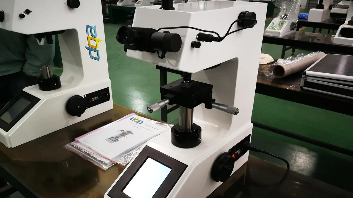

What is microhardness testing?#
Microhardness testing for case depth and coatings maps hardness gradients near surfaces using low-force Vickers or Knoop diamond indenters, typically 1 gf to 1000 gf, under ASTM E384. A traverse of small indentations from the surface inward produces a depth versus hardness profile that determines effective case depth, coating hardness and decarburization depth per AMS, SAE and customer specifications.
Microhardness testing operates on the same fundamental principle as macro Vickers or Knoop testing: a diamond indenter of specified geometry is pressed into the material under a precisely controlled load, and the size of the resulting impression is measured optically. What makes microhardness testing “micro” is the small test force, typically 1 gf to 1000 gf, and the resulting indentation diagonals that often measure only tens of microns. This small scale enables hardness evaluation of microstructural constituents, narrow surface layers and coatings without smearing the measurement across a large volume.
ASTM E384, Standard Test Method for Microindentation Hardness of Materials, governs the test method. It specifies requirements for the testing machine, indenter verification, test force tolerance, measurement system resolution and the procedure itself. For case depth and coating work, the standard is used almost exclusively in the Vickers (square-base pyramid) or Knoop (elongated rhombic-base pyramid) configuration. Vickers indents produce a value that correlates with macro Vickers and can be converted to HRC, a common language for case depth specifications. Knoop is often chosen when the layer of interest is very thin or when the hardness of a brittle coating needs to be assessed because the long, shallow penetration reduces the risk of cracking and substrate interference.
How do you select microhardness test load to avoid substrate influence?#
Microhardness test load selection for case depth and coatings is controlled by the requirement that the indentation depth should not exceed about 10 percent of the layer thickness. For coatings only a few microns thick, a 10 gf load can penetrate too deep, so Knoop indenters and loads of 10 gf to 50 gf are the normal starting point.
Choosing the right test load is the single most important decision before starting a traverse. The goal is to measure the hardness of the layer, not a composite of layer plus substrate. A basic rule of thumb: the plastic deformation zone under the indenter should not extend more than about 10% of the layer thickness. For coatings that are only a few microns thick, even a 10 gf load can penetrate too deep, making Knoop essential.
The table below provides conservative starting-point loads based on layer thickness and indenter type. These assume a typical hard coating on a softer substrate; if the coating is softer than the substrate, the same rule applies but the concern is the harder substrate raising the measured value.
| Layer Thickness (µm) | Recommended Knoop Load (gf) | Recommended Vickers Load (gf) | Indentation Depth Approx. (Knoop, µm) |
|---|---|---|---|
| 5 - 10 | 10 - 25 | Not recommended | 0.3 - 0.8 |
| 10 - 25 | 25 - 50 | 10 - 25 | 0.8 - 1.6 |
| 25 - 75 | 50 - 200 | 25 - 100 | 1.6 - 4.8 |
| 75 - 200 | 200 - 500 | 100 - 500 | 4.8 - 11 |
| >200 (or case depth) | 500 - 1000 | 500 - 1000 | 11 - 20+ |
Use extreme caution when applying a Vickers load of 10 gf to 25 gf to a 10 µm to 25 µm layer.
For effective case depth determination in carburized or nitrided steel, a 500 gf or 1 kgf Vickers load is widely used. These loads produce diagonals in the 40 µm to 70 µm range on hardened martensite, which averages over the fine microstructural features without excessive data scatter. If the case is less than about 0.15 mm (150 µm), consider dropping to 100 gf or 200 gf to preserve spatial resolution, but validate that the indentation is still sampling a representative volume.
What is the procedure for a case depth microhardness traverse?#
A case depth microhardness traverse procedure under ASTM E384 involves cutting and mounting the part perpendicular to the surface, grinding and polishing to a 1 µm or 0.25 µm finish, lightly etching, and making a spaced series of Vickers or Knoop indentations from the surface inward. Hardness values are converted and plotted against depth to find effective and total case depth.
Sample preparation for a microhardness case depth traverse#
Cut the part perpendicular to the surface of interest. Use a precision sectioning saw with coolant to avoid heat damage that could alter the microstructure. Mount in a hard phenolic or epoxy compound to preserve edge retention. For thin coatings, electroless nickel overplate can be applied before mounting to protect the edge rounding.


Prepare the cross-section using standard metallographic techniques down to a 1 µm or 0.25 µm diamond finish. Etch lightly, such as 2% Nital for steel, to reveal the case/core interface, but do not over-etch. Heavy etching can erode the edge and create a step that interferes with indentation placement.
Indentation placement and spacing for a case depth traverse#
Using a microhardness tester with a digital stage or filar eyepiece, establish a reference point at the surface. The first indentation should be placed as close as practical to the edge but respecting the minimum spacing rules. A common starting distance is 25 µm from the surface for case depths over 0.5 mm, or 10 µm for shallow cases.
ASTM E384 requires center-to-center spacing of at least 2.5 times the diagonal length of the indentation. For a Vickers indent with a 50 µm diagonal, that means 125 µm from the next indent. When near a free surface, keep the indentation center at least 3 diagonal lengths from the edge. Many labs use a geometric progression: start with 0.05 mm from the edge, then increase the step size by 0.05 mm intervals or double the spacing as the hardness curve flattens in the core.
Measurement conversion and plotting for case depth traverse data#
Record the Vickers diagonal or Knoop long diagonal at each location. Convert to hardness number using standard formulas. If the specification calls for effective case depth at HRC 50, convert the Vickers values to HRC using ASTM E140 or ISO 18265 tables. Be aware that these conversions are approximate, especially for nitrided layers and high-alloy steels; refer to the article on hardness conversion caveats for guidance.
Generate a scatter plot with depth on the horizontal axis and hardness on the vertical axis. Connect the points with a smooth line or a step function that reflects the actual measurement positions.
Effective case depth is defined as the distance from the surface to the point where the hardness drops to a specified limit, often 50 HRC (513 HV) for carburized gears per AMS 2759/1. Total case depth is the distance to the core microstructure, which can be determined by visual metallography or as the depth where the hardness curve flattens to within 5% to 10% of the core value. The microhardness traverse provides an objective, repeatable method for both.
How do you measure decarburization depth by microhardness testing?#
Decarburization depth is measured by microhardness testing through a traverse of indentations from the surface inward. The depth is reported where hardness reaches the unaffected core hardness or a specified percentage of that core value. SAE J419 defines total and effective decarburization depth by such hardness criteria, making the traverse the most functional measurement method.
Decarburization, or carbon depletion, at the surface of a steel component creates a soft skin that can severely reduce fatigue and wear performance. A microhardness traverse is the most reliable way to quantify the depth of the affected layer because it measures the functional hardness rather than relying solely on optical estimates of ferrite grain boundaries.
To perform a decarburization traverse, start indentations very close to the surface, often 10 µm to 25 µm. The hardness will typically be lowest at the surface and increase gradually until it reaches the unaffected core hardness. Specifications such as SAE J419 define decarburization depth by hardness criteria: total decarb depth is the distance to the point where hardness reaches the minimum specified core hardness, while effective decarb depth is often where the hardness reaches a certain percentage of the core, say 90%. The decarburization measurement guide covers visual and hardness methods in detail.
For the traverse itself, use a load that suits the depth of the soft layer. A 100 gf or 200 gf Vickers load works well for decarb layers up to 0.5 mm. In fully decarburized regions, the hardness may be below 200 HV; as the carbon increases, the hardness rises. Plotting this curve lets you present an unambiguous depth number that satisfies most aerospace (AMS) and automotive (SAE) requirements.
How do you test hardness of thin coatings with microhardness?#
Thin coating hardness testing by microhardness uses a Knoop indenter and a test load that keeps indentation depth below one-tenth of the coating thickness, often 10 gf or lower for a 5 µm coating. Cross-section traverses across the coating are preferred over direct surface indents because they map coating hardness while limiting substrate influence.
Hard, thin coatings (TiN, CrN, DLC, electroless nickel, hard chrome) demand special care. The coating may be only 2 µm to 10 µm thick, so the indentation must remain shallow enough that the substrate does not contribute to the measured hardness. The Bückle 10% rule is widely applied: the indentation depth should be less than one-tenth of the coating thickness. For a 5 µm coating, that translates to a maximum penetration of 0.5 µm. Such shallow indentations require loads of 10 gf or lower, and even then, Knoop is usually the only viable option because its long diagonal can be measured more accurately when penetration is minimal.
When testing thin coatings:
- Use Knoop over Vickers if the coating is under 25 µm. The Knoop indenter’s 7:1 long-to-short diagonal ratio creates a shallow plastic zone, reducing substrate effects.
- Check for cracking and delamination. Brittle coatings may develop radial or spall cracks. ASTM E384 notes that hardness values from cracked indents are invalid; report them separately.
- Cross-section traverse versus surface indent: A cross-section traverse across the coating thickness is preferable because it maps depth-dependent properties. Direct surface indentation can be used if the coating is thick enough and the substrate is hard, but it will always contain some substrate effect unless the penetration is incredibly shallow.
A practical rule for quality control is to agree with the customer on a standard load and indenter combination that has been validated against a known thickness and substrate condition. This combination then becomes part of the test specification.
How do you interpret depth versus hardness plots in microhardness testing?#
Depth versus hardness plots from microhardness testing are interpreted by locating the effective case depth at the intersection of the hardness curve with the specified limit line, such as 50 HRC or 513 HV, and by identifying the coating hardness plateau, decarburization gradient and core hardness. The plot is accompanied by a data table of distance, diagonal length and hardness value.
Key features to identify on a depth versus hardness plot#
On the plot, the horizontal axis runs from zero at the left and shows distance from the surface. The vertical hardness axis can be logarithmic or linear depending on the range.
- Effective case depth: The intersection of the hardness curve with the specified limit line, for example 50 HRC or 513 HV. Interpolate between the two points straddling the line. Report the distance to 0.01 mm.
- Coating hardness plateau: For a distinct coating, the curve will show a sharp drop at the coating/substrate interface. The hardness of the coating itself should be reported as the average of at least three well-spaced, valid indentations within the coating, with the test load clearly stated.
- Decarburization gradient: A gradual rise from the surface to the core indicates carbon depletion. Mark the total and effective decarb depths on the plot.
- Core hardness: Report the average of at least five indentations taken well away from the case or coating, typically at a load high enough to be representative of the bulk metal.
How to report microhardness traverse results#
Results must be reported with the test method (ASTM E384), indenter type, load in gf, and the conversion scale if used. Many AMS specifications for carburizing, such as AMS 2759/1 and AMS 2759/2, and nitriding require a microhardness traverse and define the exact spacing, load and reporting format. The data table accompanying the plot should list each indentation’s distance, diagonal length, and hardness value. For supplier submissions, also include the microhardness tester’s calibration date and indenter certification.
For a deeper look at the hardness scales themselves, see the Rockwell vs Brinell vs Vickers comparison.
What common pitfalls affect microhardness traverse quality?#
Common microhardness traverse quality problems include edge rounding during polishing, floor vibration, inadequate indentation spacing, incorrect diagonal measurement, unvalidated hardness conversions, indentation anisotropy and surface preparation burns. Preventing these problems requires proper mounting, vibration isolation, strict spacing rules, visual measurement confirmation and validated conversion tables on the actual material.
- Edge rounding during polishing: If the surface edge is rounded, the first indentations will fall on sloping material and produce falsely low hardness. Use an epoxy mount with a nickel overplate or apply vacuum impregnation. Check edge retention under the microscope at 200X or higher before starting.
- Vibration and shock: Microhardness testers are sensitive to floor vibrations. Vibration causes irregular indent shapes and scatter. Ensure the tester sits on a vibration-isolation table and that the loading cycle is smooth.
- Inadequate spacing: Indents placed too close together work-harden the material and raise subsequent readings. Follow the 2.5 diagonal spacing rule unconditionally.
- Incorrect diagonal measurement: Automated measurement systems can misinterpret uneven contrast or debris. Always visually confirm the measurement lines, especially on etched traverses where the grain boundary contrast can confuse edge detection.
- Using conversions without validation: Converting Knoop or Vickers to HRC for nitrided steels or stainless steels can introduce systematic error. If the specification mandates an HRC value for effective case depth, validate the conversion on the actual core material with a macro hardness test.
- Ignoring indentation anisotropy: In some wrought or rolled materials, hardness varies with orientation. Knoop indentations are more sensitive to anisotropy. Align the indenter long axis with a consistent direction, preferably the rolling or working direction, and note it in the report.
- Surface preparation burns: Overheating during grinding can temper a hardened case. Use low-pressure final grinding steps and observe the surface for heat tint. If discoloration occurs, repolish and discard the suspected area.
Key takeaways#
Microhardness testing for case depth and coatings succeeds when loads limit indentation depth to less than 10 percent of the layer thickness, indents are spaced per ASTM E384, sample edges remain sharp, and hardness conversions are validated. The result is a depth versus hardness plot that supports repeatable case depth and coating hardness decisions.
- Microhardness traverses per ASTM E384 are the primary method to determine effective case depth, decarburization depth and thin coating hardness with high spatial resolution.
- Load selection must keep the indentation depth under 10% of the layer thickness; Knoop is generally required for coatings below 25 µm.
- Maintain proper spacing (2.5 diagonals between indents, 3 diagonals from edges) and mount samples to preserve edge sharpness.
- A depth versus hardness plot is the universal report format; interpolate the intersection with a hardness limit to declare effective case depth per AMS and SAE requirements.
- Validate hardness conversions and indentation measurement accuracy on your specific microstructure to avoid submission rejections.
Entities in this article
Frequently Asked Questions
How do I choose between Vickers and Knoop for a thin coating?
Knoop is preferred for coatings under 25 microns because its long diagonal yields a shallower penetration for a given load, which minimizes substrate influence. Vickers works well for layers above 50 microns or when a direct conversion to Rockwell C is needed for case depth determination.
What is the minimum spacing between indentations on a traverse?
ASTM E384 requires center-to-center spacing of at least 2.5 times the indentation diagonal length. When approaching a surface or interface, keep the center at least 3 diagonal lengths from the edge to avoid distorted readings from the free surface.
What load should I use to measure case depth in carburized steel?
For case depth traverses, a 500 gf or 1 kgf Vickers load is common because it balances resolution with minimal scattering from microstructural features. Use a load that creates indentations large enough to average over the grain structure but small enough to distinguish the 50 HRC equivalent transition typically used for effective case depth.
How do you determine effective case depth from a hardness traverse?
Plot hardness (HV or converted HRC) versus distance from the surface. Effective case depth is the distance from the surface to the point where hardness falls below the specified limit value, often 50 HRC (513 HV) for carburized gears per AMS 2759/1. The value is interpolated between the two nearest indentations.