On this page
- What is macro etching for weld inspection?
- How are macro etch specimens extracted from a welded assembly?
- How is the surface of a macro etch specimen prepared?
- What is the procedure for etching weld cross-sections?
- What does a macro etched weld cross-section reveal?
- How does macro etching detect weld discontinuities?
- How are weld dimensions measured on a macro etch specimen?
- What is the procedure for documenting macro etch results?
- Key Takeaways
Macro Etching for Weld Inspection: Procedure and Interpretation
Macro etching reveals weld macrostructures for quality assessment. This guide covers procedure, interpretation of fusion zone, HAZ, and defects per ASTM E340.

What is macro etching for weld inspection?#
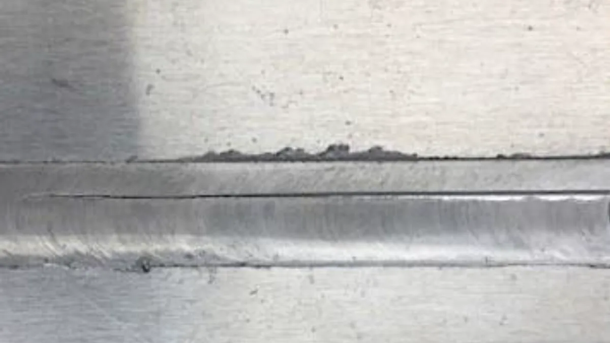
Macro etching is a low-magnification metallographic technique that reveals the weld cross-section’s macrostructure: the fusion zone, heat-affected zone (HAZ), and base metal, along with discontinuities like lack of fusion, slag inclusions, and porosity. Guided by ASTM E340, the procedure involves sectioning, grinding to a fine finish, and applying a chemical etchant that attacks different microstructural regions at different rates, creating visible contrast. When done correctly, macro etching provides a permanent record of weld quality and penetration that no non-destructive method can match.
How are macro etch specimens extracted from a welded assembly?#
Macro etch specimens must be extracted from the welded assembly in a way that preserves the true weld geometry and does not introduce thermal or mechanical damage. The cut should be made transverse to the weld axis, producing a cross-section that shows the full joint profile from one side to the other. For multi-pass welds, the section must capture all passes and the root area.
Abrasive cutoff wheels are the preferred method for sectioning ferrous materials. Use a wheel hardness matched to the alloy; a wheel that is too hard glazes and generates excessive heat, while one that is too soft wears rapidly and can smear the surface. Flood cooling during cutting is essential to prevent microstructural changes in the HAZ that could obscure the true macrostructural features. For large weldments, a bandsaw or reciprocating saw may be used for rough cutting, followed by a second, finer cutoff wheel cut to produce a specimen of manageable size.
The specimen size should be large enough to include at least 10 mm of unaffected base metal on both sides of the weld, and the cut face should be flat to within 0.25 mm across its width. If the weld is part of a procedure qualification record, the governing standard (such as ASME Section IX or AWS D1.1) will specify the number and location of macro sections required. Always mark the specimen with a unique identifier and an orientation arrow before cutting.
How is the surface of a macro etch specimen prepared?#
After sectioning, the macro etch specimen’s cut face must be ground to a flat, scratch-free finish. The goal is to remove all cutting damage and produce a surface that will etch uniformly. A sequence of progressively finer silicon carbide papers is the standard approach, starting with 80 or 120 grit to remove saw marks and ending with 320 or 400 grit. For routine macro inspection, a 400-grit finish is usually sufficient; finer polishing (600 grit or a brief diamond polish) can improve contrast for critical evaluations or photography.
Grinding must be performed with water as a lubricant and coolant. Dry grinding can overheat the surface and alter the temper of the HAZ, masking important features. Use a rotating wheel or belt grinder with a rigid backing to maintain flatness. After each grit change, rotate the specimen 90 degrees so that new scratches are perpendicular to the previous set. This makes it easy to see when all coarse scratches have been removed.
A common mistake is to skip grits or spend too little time on the coarser papers. Residual coarse scratches will hold etchant and produce dark lines that can be mistaken for cracks or lack of fusion. Inspect the surface under a stereo microscope at 10-20× magnification before etching. The surface should show a uniform set of fine, parallel scratches with no pits, burrs, or embedded abrasive particles.
What is the procedure for etching weld cross-sections?#
The macro etching procedure for weld cross-sections begins with selecting an etchant based on the base metal and filler metal. Common etchants include nital (2-5% nitric acid in alcohol) for carbon and low-alloy steels, and 10% aqueous ammonium persulfate for stainless steels. The etchant is applied by swabbing or immersion, attacking different microstructural regions to create visible contrast. ASTM E340 lists numerous macro etchants and their application methods.
| Etchant | Composition | Material | Application Method | Etching Time (s) |
|---|---|---|---|---|
| Nital 2% | 2 mL nitric acid in 98 mL ethanol or methanol | Low-carbon steel, mild steel | Swab or immersion | 10-30 |
| Nital 5% | 5 mL nitric acid in 95 mL ethanol or methanol | Medium-carbon, low-alloy steel, heat-treated welds | Swab or immersion | 15-60 |
| Ammonium Persulfate 10% | 10 g ammonium persulfate in 100 mL water | Stainless steel, duplex, nickel alloys | Swab (fresh solution) | 30-120 |
| Mixed Acid (Kalling’s No. 2) | 5 g CuCl₂, 100 mL HCl, 100 mL ethanol | Nickel-base alloys, some stainless | Immersion or swab | 10-30 |
Nital for Carbon and Low-Alloy Steels#
Nital is the workhorse macro etchant for carbon steels. It attacks ferrite preferentially, leaving cementite and pearlite colonies in relief, which creates a matte gray appearance in the weld metal and a lighter, more reflective surface in the HAZ and base metal. The concentration is chosen based on carbon content: 2% nital for mild steel, 5% for higher-carbon or quenched-and-tempered steels.
Apply nital by swabbing the surface with a cotton ball saturated with the etchant, using gentle, continuous motion. Do not let the etchant pool. Rinse immediately with water, then alcohol, and dry with warm air. Over-etching can cause pitting and obscure the fusion line. If the contrast is insufficient, re-grind lightly and re-etch for a shorter time.
Ammonium Persulfate for Stainless Steels#
Stainless steels are resistant to nital and require a more aggressive etchant. A 10% aqueous ammonium persulfate solution, applied by swabbing, selectively attacks the weld metal and HAZ, revealing the dendritic solidification structure and the fusion boundary. The solution should be freshly prepared and used at room temperature. Etching times are longer than for nital; observe the surface continuously and stop when the weld outline becomes clearly visible. Over-etching can produce a dark, smeared appearance that hides fine details.
What does a macro etched weld cross-section reveal?#
A macro etched weld cross-section reveals three distinct zones: the fusion zone (weld metal) with a dendritic cast structure, the heat-affected zone (HAZ) where the base metal was altered by heat but not melted, and the unaffected base metal showing its original wrought microstructure. These zones are examined under a stereo microscope at 5-50× magnification after etching.
Fusion Zone (Weld Metal)#
The fusion zone appears as a region of cast metal with a dendritic (tree-like) solidification pattern. The etchant reveals the columnar grain structure that grew inward from the fusion boundary toward the weld centerline. In multi-pass welds, each pass shows its own dendritic pattern, and the boundaries between passes are visible as fine lines. The fusion zone is typically darker than the base metal when etched with nital, although the exact shade depends on the filler metal composition and the heat input. The fusion boundary itself is a narrow, distinct line where the cast structure meets the transformed HAZ.
Heat-Affected Zone (HAZ)#
The HAZ is the portion of the base metal that did not melt but experienced microstructural changes due to the heat of welding. Its width depends on the welding heat input and the thermal conductivity of the base metal. In carbon steels, the HAZ often etches lighter than both the weld metal and the unaffected base metal because of grain refinement in the normalized zone near the fusion line. Farther from the weld, a darker band may appear where partial transformation occurred. The outer boundary of the HAZ is where the base metal microstructure is visually unchanged. Measuring the HAZ width is a common requirement in weld qualification.
Base Metal#
The unaffected base metal shows the original wrought microstructure: rolling lines, banding, or a uniform equiaxed grain structure depending on the product form. The etchant reveals the flow lines from prior hot working, which are especially useful for assessing whether the weld preparation removed all decarburized or surface-affected material. Any discontinuity that extends from the weld into the base metal, such as a crack or lamination, will be sharply defined against the uniform background.
For a more detailed discussion of grain structures and their measurement, see our article on Grain Size Measurement: ASTM E112 Comparison and Planimetric Methods.
How does macro etching detect weld discontinuities?#
Macro etching excels at revealing discontinuities that are planar or tightly closed, which are often missed by volumetric NDE methods. The etchant penetrates fine openings and creates a dark line or stain that is visible even when the gap is only a few microns wide.
Lack of Fusion#
Lack of fusion appears as a sharp, dark line that follows the joint geometry rather than the solidification pattern. Side-wall lack of fusion, a common defect in groove welds, shows as a straight dark line along the bevel face separating the weld metal from the base metal. Inter-run lack of fusion between weld passes appears as a meandering dark line that does not follow the dendritic growth direction. Unlike a crack, lack of fusion has a blunt tip and often contains slag or oxide films.
Slag Inclusions#
Slag inclusions appear as irregularly shaped dark pits or elongated lines, often aligned with the pass boundaries. In multi-pass welds, slag trapped between passes is a frequent finding. The etchant attacks the slag preferentially, leaving a cavity or a deeply etched region. Under the stereo microscope, slag inclusions have a glassy or granular appearance, distinguishing them from porosity.
Porosity#
Porosity appears as round, dark holes that are smooth-walled and randomly distributed or aligned along the weld centerline. The etchant enlarges the pores slightly by attacking the edges, making them more visible than on an unetched surface. Clustered porosity, or “wormhole” porosity, is readily identified. Macro etching cannot distinguish between gas porosity and shrinkage porosity; that determination requires higher magnification.
When these discontinuities are found during procedure qualification, the entire welding procedure specification must be reviewed. For a full checklist of mechanical testing and inspection requirements for weld qualification, refer to our Weld Procedure and Welder Qualification: Test Checklist.
How are weld dimensions measured on a macro etch specimen?#
Weld dimensions such as penetration depth, throat thickness, HAZ width, and reinforcement height are measured from a macro etch specimen using a calibrated stereo microscope. These quantitative measurements are required by welding codes like ASME Section IX and AWS D1.1, and are recorded to the nearest 0.1 mm or finer.
- Weld penetration depth: The distance from the surface of the joint (or the root face) to the deepest point of the fusion zone. For a full-penetration weld, this equals the base metal thickness. For a partial-penetration weld, the depth is measured at the weld centerline and at the toes.
- Weld throat thickness: The shortest distance from the root to the face of the fillet or groove weld, measured perpendicular to the weld face.
- HAZ width: The maximum extent of the heat-affected zone measured perpendicular to the fusion boundary, typically reported for both the face and root sides.
- Reinforcement height: The excess weld metal above the base metal surface, measured at the centerline.
All measurements should be reported to the nearest 0.1 mm or finer if the code requires it. When measuring penetration depth on a fillet weld, be careful to distinguish between the fusion line and the etched outline of the root pass; the true penetration is the distance from the root face to the fusion boundary, not to the edge of the visible weld metal.
What is the procedure for documenting macro etch results?#
A well-documented macro etch photograph is a permanent quality record. The photograph should be taken under diffuse, even lighting to avoid glare from the etched surface. A stereo microscope with a digital camera or a dedicated macroscope is ideal. The magnification should be chosen so that the entire weld cross-section fills the frame, with a scale bar or calibrated ruler in the image.
Key practices for consistent macro photography:
- Orient the specimen so that the weld face is at the top of the image and the root at the bottom.
- Include a label with the specimen ID, etchant used, and magnification.
- Use a neutral gray or black background to eliminate reflections.
- Capture both an overview image at 5-10× and a higher-magnification image of the root area at 15-25×.
- If the weld is too large for a single frame, take overlapping images and stitch them together, ensuring the scale remains consistent.
The final report should include the photograph, a table of measured dimensions, and a description of any discontinuities observed. Reference the applicable welding standard and the acceptance criteria used. For procedure qualification, the report becomes part of the Procedure Qualification Record (PQR). For production welds, it serves as objective evidence of conformance.
Macro etching complements other mechanical tests that are often required in weld qualification, such as tensile and bend tests. For a broader understanding of the mechanical testing landscape, see our Mechanical Testing of Metals: The Complete Guide.
Key Takeaways#
- Macro etching per ASTM E340 is a destructive test that reveals the weld cross-section’s macrostructure, including the fusion zone, HAZ, and base metal.
- Proper sectioning with flood cooling and stepwise grinding to at least 400 grit are essential to avoid artifacts that can be mistaken for defects.
- For carbon and low-alloy steels, use 2-5% nital; for stainless steels, use 10% aqueous ammonium persulfate, applied by swabbing and followed by immediate rinsing.
- The fusion zone shows a cast dendritic structure, the HAZ appears as a light-etched band of altered base metal, and the unaffected base metal retains its original wrought structure.
- Discontinuities such as lack of fusion, slag inclusions, and porosity appear as dark lines, irregular pits, or round holes that are sharply defined after etching.
- Quantitative measurements of penetration depth, throat thickness, and HAZ width must be made with a calibrated scale and reported to code requirements.
- Photographic documentation with scale bars, proper orientation, and consistent lighting creates a permanent, auditable record of weld quality.
Entities in this article
Frequently Asked Questions
What is macro etching in weld inspection?
Macro etching is a destructive test that reveals the weld cross-section’s macrostructure by applying a chemical etchant to a polished surface. It highlights the fusion zone, heat-affected zone, and base metal, making discontinuities like lack of fusion, slag, and porosity visible to the naked eye or at low magnification.
Which etchants are used for macro etching steel welds?
For carbon and low-alloy steels, 2-5% nital (nitric acid in alcohol) is most common. For stainless steels and nickel alloys, a 10% aqueous ammonium persulfate solution or mixed acids are used per ASTM E340.
How do you measure weld penetration depth from a macro etch?
After etching, the specimen is placed under a stereo microscope or macroscope with a calibrated scale. Penetration depth is measured from the original joint surface to the deepest point of the fusion zone, typically recorded as the average of multiple readings or the maximum value.
What defects can macro etching detect that radiography might miss?
Macro etching can reveal tight lack of fusion defects, especially side-wall lack of fusion, and fine slag lines that are often difficult to detect with radiography. It also shows the true fusion line profile and HAZ extent, which radiography cannot.